Creator Program API Reference
This page will explain how to use the Program Creator. To get started you will need to have one of our Wi-Fi enabled products and access to the onboard we portal.
Inputs
Section titled “Inputs”
The input block will define all inputs that will be needed for your device. The input block will take 4 parameters that are required.
| Parameter | Input description | Default Value |
|---|---|---|
| Name | The human readable comment of the input. | in1 |
| Pin | The pin number that the input will represent. | 0 |
| Type | The type of input. Either analog or digital. | analog |
| Pull | Either pull up or pull down. If no pull is needed, use DNP (Do Not Pull) | DNP |
Outputs
Section titled “Outputs”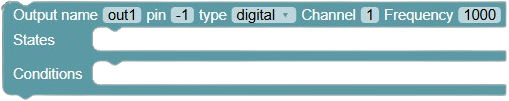
The output block will define all the outputs that will be needed for your device. The output block will take 3 parameters that are required to create a valid output. The output block will fit inside of the input block and will take states and conditions blocks will fit inside. When PWM is selected, the output block will require a channel and frequency input as well.
| Parameter | Input description | Default Value |
|---|---|---|
| Name | The human readable comment of the output. | out1 |
| Pin | The output pin to drive. Select -1 for no output pin to be driven. | -1 |
| Type | The type of output. Either digital or PWM. | digital |
| Channel | PWM channel to use if type is set to PWM. There are 10 channels available for use. | 1 |
| Frequency | The frequency in Hz of the PWM channel if type is set to PWM. | 1000 |
If the pin number is -1, the “type”, “channel”, and “frequency” fields have no effect. If a pin number is selected and the type is digital, the “channel” and “frequency” fields have no effect.
States & Conditions
Section titled “States & Conditions”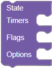
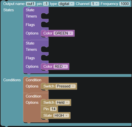
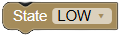
The state blocks are used to perform device actions. The condition blocks are used to set conditions to operate the device. State and condition blocks are placed within output blocks and are numbered state1, state2, condition1, condition2, etc. A maximum of 10 states and conditions can exist per output.
When the conditions in condition1 are satisfied, state1 activates. A condition triggers when all the options are satisfied.
States are used to change images or text on the LCD, change the backlight color, drive the I/O pins, operate timers, change flag variables, etc.
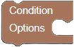
There are multiple options for conditions such as reading the switch press, pins, timers, and flags.
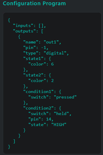
For example, an output is configured as follows:
- State 1 is changing the backlight green.
- State 2 is changing the backlight red.
- Condition 1 is when the switch is pressed.
- Condition 2 is when the switch is held and pin 14 is HIGH.
Therefore, when the switch is pressed, the backlight turns green. When both pin 14 is HIGH and the switch is held, the backlight turns red.
State Options
Section titled “State Options”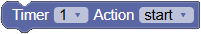
Operates a timer. There are 8 different timers available for use. The actions are:
- Start - When a timer is started, it counts down from its set duration.
- Stop - When stopped, the timer is set to 0.
- Restart - Restarts the timer with its set duration.
- Pause - Pauses a timer.
- Resume - Resumes a timer if paused.
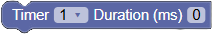
The value in milliseconds to set a timer when it is started.
Operation to modify a timer’s duration in milliseconds. The options are:
- = , sets the duration to a specific value.
- += , add a value to the duration.
- -= , subtract a value from the duration.

Flags are integer variables that can be modified and read. There are 12 flags available for use. The options are:
- = , sets the flag to a specific value.
- += , add a value to a flag.
- -= , subtract a value from a flag.
- ++ , increment the flag value by 1.
- — , decrement tht flag value by 1.
Images
Section titled “Images”
Type the name of the image only. If the image name is not found on the flash switch, you will receive an error code. Please see the product page for the correct error code.
Output
Section titled “Output”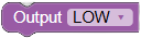
Sets the output pin defined in the output block either LOW or HIGH. The output “type” must be set to “digital” for this functionality to work.

Sets the duty cycle in Hz of the PWM channel associated with the output pin defined in the output block. The output “type” must be set to “PWM” for this functionality to work.
On Duration
Section titled “On Duration”
Sets the output pin HIGH for the set duration in ms. If this block is used, it will override using the “output” and “duty” state blocks.
Off Duration
Section titled “Off Duration”
Sets the output pin LOW for the set duration in ms. If this block is used, it will override using the “output” and “duty” state blocks.
Clear Background
Section titled “Clear Background”Clears the pixels before putting text or images. Don’t use if you want text to superimpose over previous pixels.
Set Text
Section titled “Set Text”
Sets text to rows 1, 2, or 3 on the switch. If row 3 is selected, the font will be 6x8.

Sets the font size for text. There are two sizes: 6x8 and 9x12. 6x8 can fit six characters per row in three rows. 9x12 can fit four characters per row in two rows.
Invert
Section titled “Invert”
Inverts the pixels of the text or image placed.
Set Color
Section titled “Set Color”
Sets the backlight to a static color.

Sets two alternating and blinking colors. The duration of each color is set. This option overrides the “color” block. Durations are in milliseconds.
Brightness
Section titled “Brightness”
Sets the backlight brightness from levels 1-10. The default level is 10.
Contrast
Section titled “Contrast”
Sets the LCD contrast or the darkness of the pixels from levels 1-10. The default level is 7. It is not necessary to change the contrast. Adjusting the contrast is only needed if you see changes in the display due to extreme temperatures.
Stopwatch
Section titled “Stopwatch”
Operates the stopwatch. The stopwatch is the length of time the unit has been on since power-up. The stopwatch can be seen with the display stopwatch block. The actions to operate the stopwatch are:
- Start - When the stopwatch is started, it begins counting up. The stopwatch automatically starts on power-up.
- Stop - When stopped, the stopwatch is set to 0. The stopwatch is reset when the unit is powered off.
- Pause - Pauses the stopwatch.
- Resume - Resumes the stopwatch if paused.
Display Analog Value
Section titled “Display Analog Value”
Displays an analog reading from a pin on the LCD. Data can be displayed in various formats:
- Display Analog Voltage: converts and shows the reading as a voltage from 0-3.3V.
- Display Analog Percent: converts and shows the reading as a value from 0-100%.
- Display Analog BarGraph: converts and shows the reading as a bar graph animation in one row.
- Display Analog Fraction: converts and shows the reading as a fraction. The “levels” field sets the denominator or number of steps.
- Display Analog Value: shows the raw 12-bit analog value from 0-4095.
Display Timer
Section titled “Display Timer”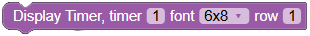
Displays the value of the selected timer in seconds.
Display Flag
Section titled “Display Flag”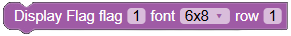
Displays the value of the selected flag.
Display Stopwatch
Section titled “Display Stopwatch”
Displays the value of the stopwatch in format HH:MM:SS. The stopwatch begins automatically on startup and is reset on power reboot.
Display Stopwatch Days
Section titled “Display Stopwatch Days”
Displays the value of the stopwatch days. Every 24 hours that the stopwatch is on, a day is incremented.
Condition Options
Section titled “Condition Options”
The input pin to read.
Digital state of the input pin to read.
Threshold
Section titled “Threshold”
Threshold value to read from the analog input pin. Must be used with the “comparison” block.
Comparison
Section titled “Comparison”
Set the comparison to be less, greater, or equal to the value set in the “threshold” block.
Threshold Range
Section titled “Threshold Range”
Threshold range to read from the analog input pin. The range is the 12-bit value 0-4095.
- Max - Max number of the analog range.
- Min - Min number of the analog range.
Threshold Voltage
Section titled “Threshold Voltage”
Threshold range to read from the analog input pin. The range is 0-3.3V.
- Max - Max number of the analog voltage.
- Min - Min number of the analog voltage.
Threshold Percent
Section titled “Threshold Percent”
Threshold range to read from the analog input pin. The range is 0-100%.
- Max - Max number of the analog percent.
- Min - Min number of the analog percent.
Switch
Section titled “Switch”
Reads the state of the SmartDisplay button. The options are pressed, released, held, or held released.

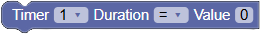
Reads the state of the timer. The options are:
- Expired - A timer is expired when it counts down to 0.
- Running - When the timer is counting down.
- Paused - When the timer is paused.
- Stopped - When the timer is stopped.

Reads the value of a flag.
Demo Program Example
Section titled “Demo Program Example”You can find examples using the Program Creator that replicate the behavior of the default demo program on the IS-S0110DEM evaluation kit.