NKK Logo Splash Screen
Displays on power-up. Stays on for three seconds. The backlight blinks white and yellow.
All Rights Reserved Worldwide
NKK Switches makes no warranty for the use of these products and assumes no responsibility for any errors which may appear in this document, nor does it make a commitment to update the information contained herein. SmartDisplay is a trademark of NKK Switches.
The Single Switch Solution is a compact device that can both monitor and control an industrial process independently or in conjunction with other controllers.
The IS-S0110-2 is a non-wireless alternative to the IS-S0110 Single Switch Solution. The main differences with this part number are:
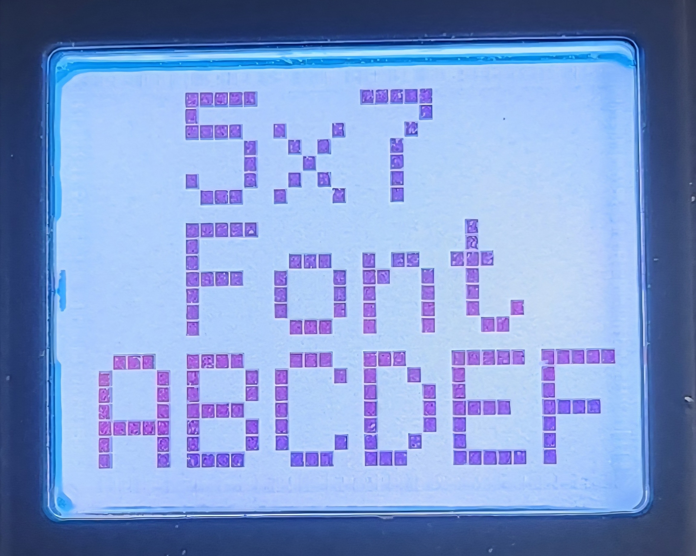
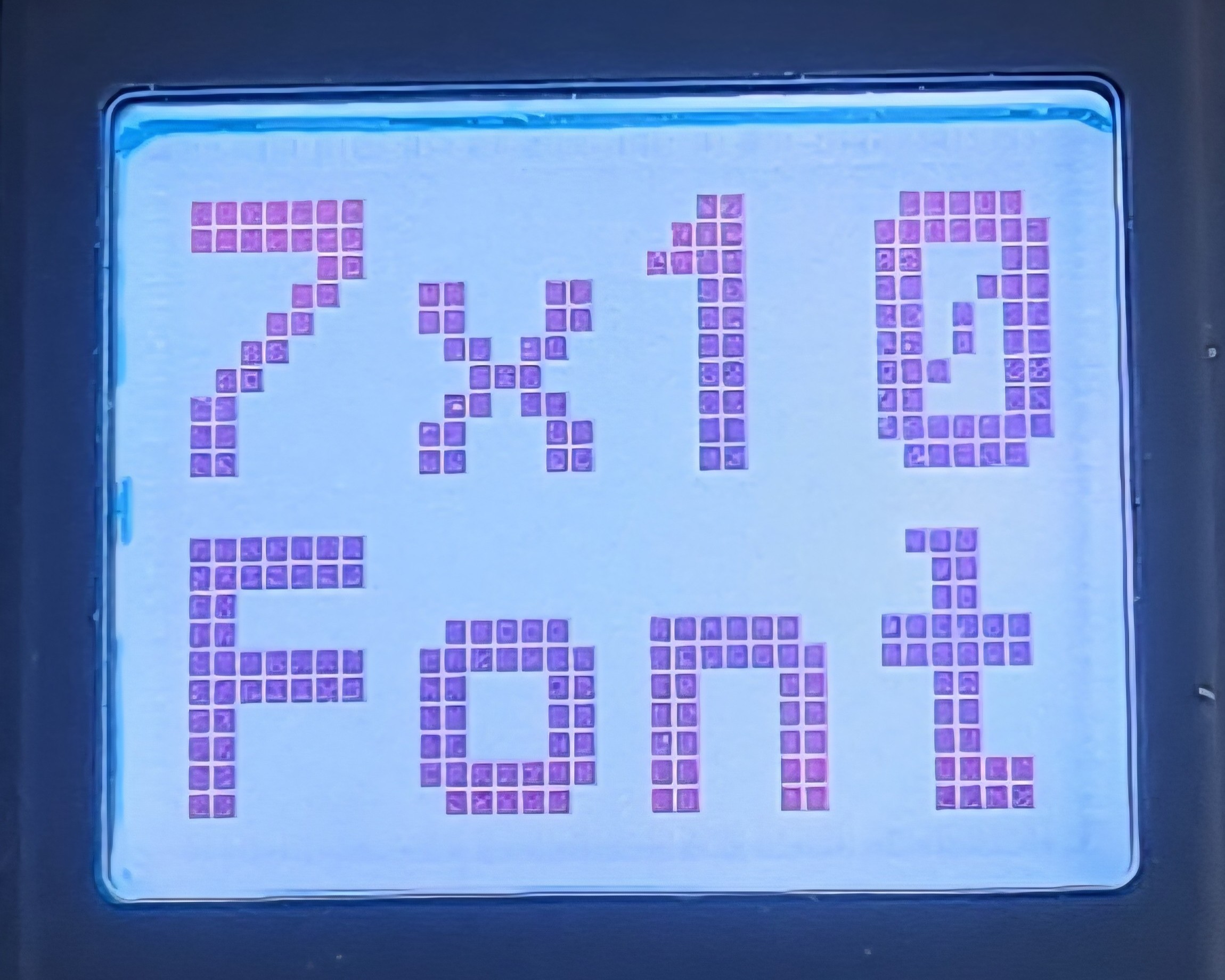
The 36x24 pixel LCD display can display graphics or characters while the backlight color options allow for status color schemes and modes of operation. In addition to the on-board flash, there are two look-up fonts (5x7 and 7x10) on board to create images based on characters. Up to 3 lines of 6 characters in font 5x7 or up to 2 lines of 4 characters in font 7x10 can be displayed.
14 micro-controller pins are available for use. Pins can be configured to be analog inputs or digital inputs/outputs:
The SmartDisplay push button presses can be used for toggling between statuses or menus and holding the push button can be used for selecting options.
SPI, I2C, and UART communications are possible.
The Single Switch solution is useful in many applications where complex information needs to be displayed while minimizing design and installation time and complexity. Contact engineering@nkkswitches.com for application consultation.
Features:
The IS-S0110-2 source code is available for customers to write their own programs. The source code is written in C++ using PlatformIO in Visual Studio Code. Please see the section Programming for more information.
Alternatively, the IS-S0110-2 source code can be configured by NKK Switches per request. Please contact engineering@nkkswitches.com for an application consultation.
The device source code is configured per application. The user can upload images and configure what images, text, and actions they want to see. The device would then be programmed and loaded with the images, actions, and responses ready to be used. The customer would then simply need to install the device into their application. Please contact NKK Switches for any support with your application. If the current product does not meet your application, we can add features that meet your requirements.
Application Examples:
A Single Switch Solution is hooked up to a device that drops jellybeans into a bag and a counting sensor. When the Single Switch Solution counts out a fixed number of beans it sends signals to stop the jellybeans from dropping, move the bag out of the way, seal the bag and get the next bag.
A Single Switch Solution is used to monitor two voltages and two currents. Pressing the switch steps through displaying the status of each of the four measurements. When the voltages or currents exceed a preset warning range the display blinks to warn the operator. When the voltages or currents reach a danger range not only does the display turn red it also sends signals to shut down the system. The warning and shut down values for each measurement are user defined and can be modified by pressing and holding the switch while displaying the measurement.
A Single Switch Solution is hooked up to engine sensors to display fuel, water, oil, and temperature. Pressing the switch cycles through and displays the four statuses. When any of the statuses are outside normal the display blinks amber to warn the operator. When any of the statuses are in danger range the display blinks red.
The non-wireless version of the Single Switch Solution is available as part number IS-S0110-2.
An evaluation kit can be ordered for testing. The evaluation kit part number is IS-S0110-2DEM and includes:
The evaluation kit IS-S0110-2DEM comes preprogrammed for demonstrating the Single Switch Solution capabilities. The source code provided is also written for this evaluation kit. Please see the section IS-S0110-2DEM Evaluation Kit for more information.
The Single Switch System incorporates an IS15BBFP4RGB in an AT548 panel mount accessory soldered to a small controller PCB. The microcontroller used is the ESP32-PICO-V3-02.
Power input: 5V to 15V. The absolute maximum load is 1A.
IS-S0110-2 Photos:
Application Interface Header (J1) is a 2x9 header 0.1” x 0.1” for application connections.
Application Interface Header (J1) is a 2x9 header 0.1” x 0.1” for application connections.
| Pin# | Pin Name | Possible Function | Notes |
|---|---|---|---|
| 1 | IO33 | GPIO / PWM / ADC | Can be digital input/output, PWM output, or analog input. |
| 2 | IO32 | GPIO / PWM / ADC | Can be digital input/output, PWM output, or analog input. |
| 3 | IO26 | GPIO / PWM | Can be digital input/output, PWM output. |
| 4 | IO25 | GPIO / PWM | Can be digital input/output, PWM output. |
| 5 | IO12 | GPIO / PWM | Can be digital input/output, PWM output. |
| 6 | IO14 | GPIO / PWM | Can be digital input/output, PWM output. |
| 7 | IO15 | GPIO / PWM | Can be digital input/output, PWM output. |
| 8 | IO13 | GPIO / PWM | Can be digital input/output, PWM output. |
| 9 | IO2 | GPIO / PWM | Can be digital input/output, PWM output. |
| 10 | I35 | GPI / ADC | Input only. Can be digital or analog input. |
| 11 | I34 | GPI / ADC | Input only. Can be digital or analog input. |
| 12 | I39 | GPI / ADC | Input only. Can be digital or analog input. |
| 13 | I38 | GPI / ADC | Input only. Can be digital or analog input. |
| 14 | I37 | GPI / ADC | Input only. Can be digital or analog input. |
| 15 | GND | Ground | |
| 16 | 3V3 | 3.3V output generated by the onboard circuit. If powering external devices, the maximum current drawn cannot exceed 1A. | |
| 17 | GND | Ground | |
| 18 | VIN | Input voltage 5V to 15V. The unit can also be powered via the USB C connector with 5V. |
Header J2 or the USB C connector can be used for UART TX and RX communication.
All the I/O pins are directly connected to the microcontroller pin. There is no safety circuit due to lack of space. If the application signals are not stable appropriate safety measures should be implemented in the application or interface board.
Some applications require an interface board for converting the analog input to proper voltage or turning on relays that require more current. NKK can design interface boards for new applications.
The IS-S0110-2DEM is a demonstration unit for the IS-S0110-2 Single Switch Solution. Below are the current features:
JIN - Connector for IS-S0110-2.
J1 - 2x14 header for connecting board peripherals to the IS-S0110-2 pins.
AN1-AN4 - Potentiometers for analog input.
DIG1-DIG5 - Toggle switches for digital input.
LED1-LED5 - LEDs for digital output.
VIN - Power input 5V to 15V.
3V3 - 3.3V output generated by the onboard circuit. If powering external devices, the maximum current drawn cannot exceed 1A.
GND - Ground.
The unit has four potentiometers that simulate analog input signals, five toggle switches that simulate digital inputs, and five LEDs that simulate digital outputs. The demo program configures the pins as:
| Pin# | Pin Name | Function | Pin Mode | Notes |
|---|---|---|---|---|
| 1 | IO33 | LED1 | Output | Connected to LED1. |
| 2 | IO32 | LED2 | Output | Connected to LED2. |
| 3 | IO26 | LED3 | Output | Connected to LED3. |
| 4 | IO25 | LED4 | Output | Connected to LED4. |
| 5 | IO12 | LED5 | Output | Connected to LED5. |
| 6 | IO14 | DIG1 | Input, pull-down | Connected to toggle switch 1. |
| 7 | IO15 | DIG2 | Input, pull-down | Connected to toggle switch 2. |
| 8 | IO13 | DIG3 | Input, pull-down | Connected to toggle switch 3. |
| 9 | IO2 | DIG4 | Input, pull-down | Connected to toggle switch 4. |
| 10 | I35 | DIG5 | Input, pull-down | Connected to toggle switch 5. |
| 11 | I34 | AN1 | Input | Connected to potentiometer 1. |
| 12 | I39 | AN2 | Input | Connected to potentiometer 2. |
| 13 | I38 | AN3 | Input | Connected to potentiometer 3. |
| 14 | I37 | AN4 | Input | Connected to potentiometer 4. |
| 15 | GND | Ground | ||
| 16 | 3V3 | 3.3V output generated by the onboard circuit. If powering external devices, the maximum current drawn cannot exceed 1A. | ||
| 17 | GND | Ground | ||
| 18 | VIN | Input voltage 5V to 15V. The unit can also be powered via the USB C connector with 5V. |
VIN is 5-15V DC and can be connected through the 2-pin connector labeled VIN (top is PWR, bottom is GND), or the 2.54mm header.
Upon power-up, the display shows the NKK Switches logo. After 3 seconds it will then display the battery charge image. Pressing the button loops through eight simulated functions:
NKK Logo Splash Screen
Displays on power-up. Stays on for three seconds. The backlight blinks white and yellow.
Battery Charge
AN1 input is displayed as a percentage from 0% to 100%.
12-bit Stepper
AN2 input is displayed as a value from 0 to 4095 indicating the 12-bit analog resolution. A bar graph animation also updates based on the value. The backlight is cyan. The LEDs also light up based on AN2.
Voltmeter
AN3 input is displayed as a voltage from 0 - 3.3V. The backlight is white.
Rotary Stepper
AN4 input is displayed in steps from 0/16 to 16/16. The backlight is blue.
Timer
Operates a countdown timer. The backlight is green when the timer is running and yellow when not running.
Counter
Keeps track and displays a counter value. Resets to zero when power is off. The backlight is magenta.
Stopwatch
Displays the time the unit has been powered on. The backlight is white when running, and yellow when not running.
Demo Version
The current demo program version. The backlight is white.
Backlight Brightness Adjustment
Adjusts and displays the backlight brightness from 1 to 10.
LCD Contrast Adjustment
Adjusts and displays the LCD contrast from 1 to 10.
Opening the source code:
To use the bmp_to_hex.py script, Python 3.13 or higher must be installed on your computer. Download Python 3.13 or higher from the Microsoft Store or from https://www.python.org/downloads/.
NKK SWITCHES LIMITED WARRANTY AND LIMITATION OF LIABILITY
The following limits our liability. Please read.
NKK Switches hereby warrants this product against any and all manufacturing defects for a period of one year from the date of sale of this product to the original end user. NKK Switches’ liability in the event of such defect is limited to repair or replacement of the defective products. NKK Switches disclaims any liability or warranty obligation with respect to any product that is misused, damaged by any user, or not used in conformity with all applicable product specifications.
NKK SWITCHES HEREBY DISCLAIMS ANY WARRANTY, EXPRESS OR IMPLIED, OTHER THAN THAT CONTAINED HEREIN. NKK SWITCHES EXPRESSLY DISCLAIMS THE WARRANTIES OF MERCHANTABILITY AND FITNESS FOR A PARTICULAR PURPOSE, AND SHALL HAVE NO LIABILITY BASED ON OR ARISING FROM ANY CLAIM OF SUCH WARRANTY.
NKK Switches shall have no liability to any person for any incidental, consequential, special, punitive, or other damages of any kind whatsoever relating to any use of this product.
USE OF THIS PRODUCT IN CONNECTION WITH ANY LIFE CRITICAL APPLICATION IS NOT RECOMMENDED.